Why Build a Lathe Steady Rest
I have been working on restoring a carnival ride for the last few months, the King Supersonic Rocket Ride. We pulled the main drive spindle a while back and discovered some scoring and damage to the bearing surfaces. There's also a sleeve at the bottom- that needs to come off. It's not supposed to be welded to the shaft.
I've been trying to figure out how to fix these issues ever since.
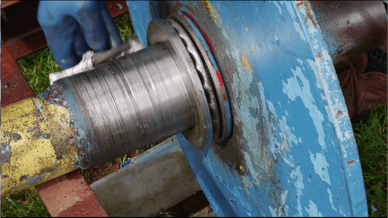
I have a lathe, but it can only swing a 13 inch diameter and this shaft has a 24 inch diameter disc welded to the end.
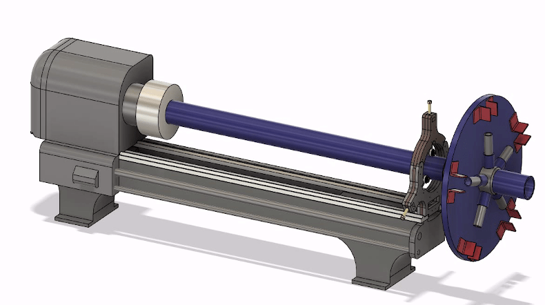
Then it occurred to me that if the shaft is long enough, and my lathe bed is short enough, maybe I could just hang the disc off the end of the lathe.
Only problem is I don't have any way to support the shaft that far out. This lathe didn't come with a steady rest.
Steady rests for my lathe show up for sale on eBay from time to time but I've never needed one until now, and they always sold for more than what I was willing to spend for an accessory I didn't need.
Designing The Steady Rest
About that time, ads started popping up on Facebook for the services of a company called OSHcut. It's a laser cutting service.
I started designing a steady rest that could be made out of pieces cut from half-inch steel and bolted together. Sort of laminated like plywood except steel. I came across a limitation in the design. My desired hole sizes were too small to burn in 1/2" plate. For this reason I switched to quarter inch plate doubled up.
As I got closer to the final design, I started printing out paper versions and used them to fine tune the center point. This is going to be a really expensive paper weight if I make a mistake.
I went through 48 design revisions over the course of a month before I was confident enough in my design to upload it to OSHcut.

How Does OshCut Laser Cutting work?
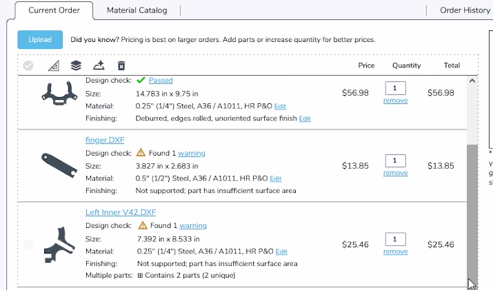
OSH-Cut has clearly invested a lot in their website to make the process painless. You upload your DXF files either one at a time or all at once, and the website analyzes your files. You then go through the files specifying the material you wish to use.
My order was a mixture of 1/4" & 1/2" parts. I had to double up the order of 1/4" parts to get the 1/2" final thickness.
If OSH Cut finds any problems, it'll flag the files and you can check whether they're just warnings or real show stoppers. The site warned me about a potential for overheating the part. It also wanted me to know that it was recognizing two separate parts in some of my files and this was correct.
In the next step, OSHcut analyzes the parts as a group and tries to nest the pieces to save you money over the original estimate. Speaking of money, I should point out here that I am in no way sponsored by OSH-Cut. I found the site through their online advertising, and I paid full price for these parts.
Assembling the Steady Rest
So my plan here is to stack all these parts up. What I want to do is cut 1/8" brass rod and pin them all together. This will hold them all in alignment so I can gang drill them.
I designed these plates with 1/8" holes. After pinning with 1/8" brass dowels, I enlarged them with a #7 drill to get my tap size for the 1/4" bolts I intend to use. As the holes are enlarged, the 1/8" pins are replaced with #7 drill bits (that was the only .201" rod I had on hand).
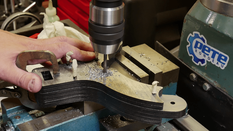
Once I have them all drilled, then I take the stack apart and I just tap the bottom plate for 1/4-20. The tapped plate is removed from the stack and then I re-drill all these for 1/4" through holes. So that gives me my alignment, and the #7 pins are replaced with 1/4" pins.
So it's kind of a tedious process, but I think it gives me the best results.
I ended up doing a lot of test fitting, proving out the design as I went along. So I assembled and disassembled this thing far more than actually necessary.
(Paid Links)
As an Amazon Affiliate, I Earn From Qualifying Purchases.Amazon and the Amazon logo are trademarks of Amazon.com, Inc, or its affiliates
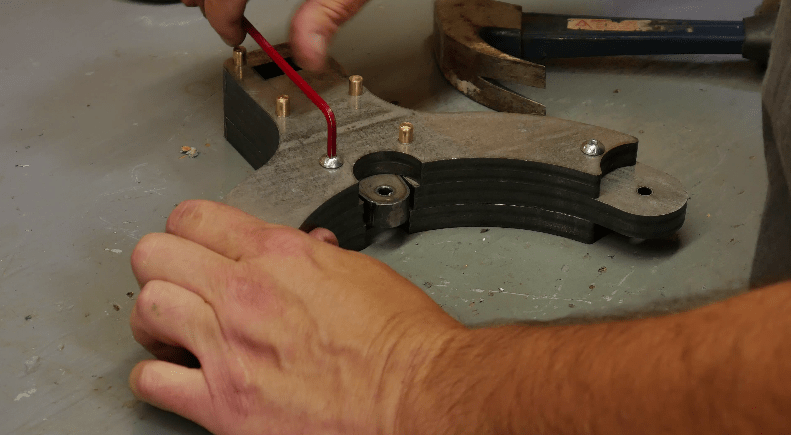
Next the bearing support fingers are drilled and tapped for 3/8-16 shoulder bolts.
As always I will leave links down below in the video description to some of the tools and supplies I used throughout this project.
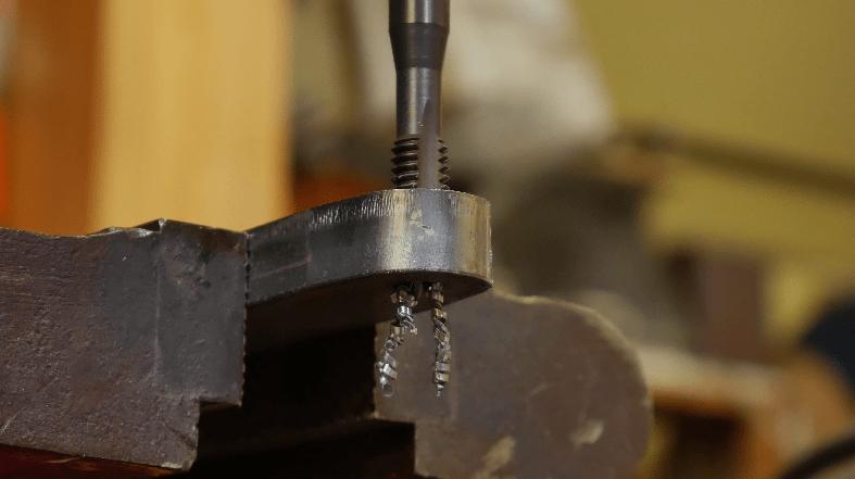
I turned a ball on the end of three 1/2" bolts for the support finger adjusters. I used a combination of a form tool and a bit of just eyeballing it. This way I didn't need to tap a deep hole in each finger.

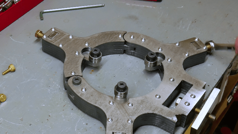
So fully assembled, this steady rest weighs exactly 30 pounds, it's a pretty good chunk of steel.
In addition to supporting the work piece, I'm hoping that amount of mass will help to dampen any vibrations.
Does it work?
So this really couldn't have worked out much better.
If my lathe had been longer, or that shaft had been either longer or shorter, or if that plate on the shaft had been bigger- none of this would have worked out.
This project took me the better part of a month from beginning to end. In the beginning I spent a lot of time looking at other shop built steady rests, but all of them required welding and welding is just not my forte. I also made some decisions so that I didn't have to tap any holes deeper than half an inch.
The ad for OSH Cut came along just at the right time to prod my brain into thinking about making a steel sandwich type construction.

Building a Steady Rest: Final Thoughts
I'm not going to lie, I have quite a bit of money wrapped up in this thing- probably about $600 just in parts. But that's fairly comparable to what I've seen the OEM steady rest sell for,(if if not even more). And my steady rest actually has a greater capacity than the OEM so it's all relative.
If I had access to a CNC plasma cutter, I could have saved myself some money. But I have no complaints about the quality of the product I got from OSH-cut. And if in the future another project presents itself, I would not hesitate to use OSHCut again.
The next step is to create some tooling that's going to allow me to clean up the bearing at the top of the shaft. But that is a project for another day.
